Spannerhead Dot ComSpannerhead.com

Posts filed under ‘Technical Curiosities’

Technical Curiosities:
Opel’s Cam-In-Head Engine

May 3, 2013 by Matt

Opel Cam In Head CIH Engine Motor GT Manta

As with single-point fuel injection, the design of Opel’s cam-in-head (CIH) engine was an attempt to bridge the old and the new, to incorporate some up-and-coming features while using as many existing parts as possible. It’s a transitional form, as it were, between ’60s and ’80s tech.

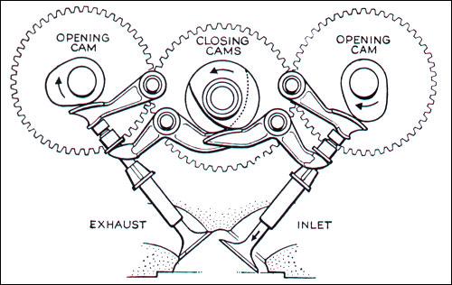
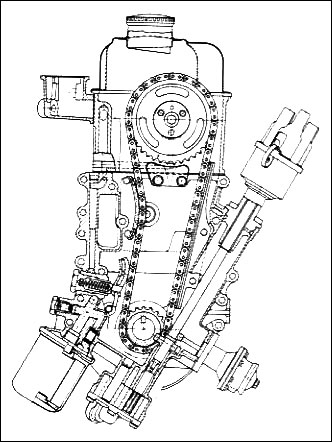
Fitted to the 1.9l, 4-cylinder blocks of the engines of Opel’s GT and Manta coupes, among others, the CIH head is a hybrid of overhead-cam and pushrod technology. The camshaft is located in the cylinder head, as in an OHC engine, but the valvetrain still uses a pushrod setup’s rocker arms and lifters. It’s as if someone had taken a pushrod design and simply moved the cam upward until the rods themselves were rendered superfluous.

Opel Cam In Head CIH Engine Motor

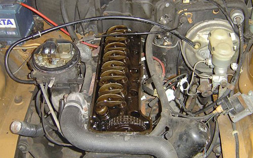
Advantages? The CIH engine was obviously an easier sell to Opel’s corporate overlords at GM, reusing as it did much existing pushrod valve gear while still offering some of the benefits of a true OHC engine. The valvetrain is more compact than in a pushrod engine and its associated inertia is much less, allowing a redline north of 10,000 rpm for race-prepped CIH engines with roller rockers and suitable springs and cam profile. Hydraulic lifters can be easily used, and in case they aren’t, valve adjustments are much more straightforward than they would be if the cam operated directly on the lifters. And significantly for the Opel GT, with its low-profile hood, the location of the camshaft farther down meant the engine’s overall height is lower than if the camshaft were truly overhead.

Opel Cam In Head CIH Engine Motor Schematic Diagram Drawing Layout Timing Chain Gear Sprocket

Downsides of the CIH engine mainly revolve around the standard limitations of a non-crossflow, 2-valve design, including relatively poor airflow and necessary compromises in combustion chamber design. Also, the cylinder head casting is relatively complex, which introduces a risk of cracking, and the head was only ever made out of cast iron, incurring a weight penalty over an aluminum head. And whatever the valvetrain’s inertial advantages over a pushrod design, there still exists considerably more valve gear than a more direct OHC layout.

Opel’s cam-in-head engine was a stepping stone, but a unique and noteworthy one.

Image credits: curbsideclassic.com

Editor’s note: This post is part of an ongoing series spotlighting obscure automotive engineering solutions. Read the other installments here:

19 Comments on Technical Curiosities:
Opel’s Cam-In-Head Engine

Technical Curiosities: Nivomat Dampers

April 8, 2013 by Matt

Volvo 780 Bertone Silver Rear

Editor’s note: As a point of clarification, I will be using the more technically correct term “dampers” to refer to what are normally, but misleadingly, described as “shock absorbers.”

Fitted prominently to the Volvo 760 sedan and 780 coupe, among many others including Rovers, Opels and Mitsubishis, Nivomat dampers should be more well known. But they seem to remain an obscure detail uncovered only by new owners of cars fitted with the system, and then usually only when it fails.

Nivomat Shock Absorbers Dampers

A combination of the French words niveau (level) and automatique, Nivomat dampers combine the function of the car-supporting spring and damper into one self-contained unit. As a result, they can be a source of particular frustration when they go bad, since the whole unit must be replaced, unlike a conventional suspension which isolates failure to either the spring (uncommon) or damper (more common). Not only that, Nivomat dampers’ relative rarity compounds the challenge by making parts that much more difficult to source and expensive.

Does the Nivomat system have any redeeming qualities? Absolutely; as mentioned, the units combine springs and dampers, but more than that, as implied by the name, they automatically level the car regardless of the load conditions. No more sagging rear end when the back seat and trunk are fully loaded—the Nivomats’ internal pressure rises to compensate and restore the normal ride height. It’s worth noting, as well, that most, if not all applications fitted the system only to the rear wheels, leaving the fronts with a conventional spring-and-damper setup.

Nivomat Shock Absorbers Dampers Diagram Drawing Schematic

The Nivomat system is hardly the only self-leveling suspension (SLS) on the market—BMW and Mercedes, just to name two, developed their own SLS systems—but what truly sets it apart is its completely self-contained design. Where other SLS systems require a support network of pumps, lines and valves, raising the part count and drawing (an admittedly small amount of) power from the engine, a Nivomat damper has an internal pump and relies on car’s normal up-and-down suspension movement as it drives for the energy needed to operate, much like a self-winding watch depends for its power on the movement of the wearer’s arm. It’s a remarkably clever design that harnesses what would other be wasted energy in service of a useful function.

Sadly, as widespread as they were, Nivomat dampers never really became mainstream. The system persisted for 20+ years, but modern electronic suspension setups eventually eclipsed the Nivomat system’s mechanical novelty.

Image credits: netcarshow.com, wardsauto.com, ipdusa.com

Editor’s note: This post is part of an ongoing series spotlighting obscure automotive engineering solutions. Read the other installments here:

2 Comments on Technical Curiosities: Nivomat Dampers

Technical Curiosities:
The Desmodromic Valve

February 8, 2013 by Matt

Desmodromic Valves Valvetrain Stem Cam

Much like our earlier installment of the Technical Curiosities series discussing the Laycock de Normanville overdrive, I couldn’t not talk about desmodromic valves for the awesomeness of the name alone.

In essence, what we have here is a valve not only opened using positive mechanical pressure from a camshaft lobe (as in nearly every conventional reciprocating piston engine), but also closed by a camshaft lobe and follower, doing away with the valve spring. With precise timing, one lobe clicks the valve open; the other slams it closed.

By eliminating the valve spring, all possibility of valve float is removed. Valve float occurs in a conventionally-sprung valvetrain arrangement at high rpm when a valve spring is unable to pull the valve shut quickly enough, disrupting timing and in extreme cases allowing the valve to contact the piston, leading to their mutual destruction. Engines with desmodromic actuation can thus rev higher without the threat of internal damage, and the multiple camshaft arrangement allows for slightly more sophisticated valve opening and closing profiles.

Desmodromic Valves Valvetrain Stem Cam Diagram Schematic Drawing Illustration

The downsides of the a desmodromic valvetrain include added complexity, twice as much mechanical noise (clicking and tapping and such) as a conventional setup, and more required maintenance in the way of valve adjustments. Also, if maintenance is neglected and the clearance between the closing cam lobe and follower is allowed to become too large, the valves might not held fully closed, leading to a whole host of running problems.

In spite of its advantages, the configuration has only been adopted by a few manufacturers, most prominently Italian motorcycle firm Ducati, who use desmodromic valves in their bikes to this day. On the automotive side, only Mercedes, back in the 1950s, designed a handful of racing engines (fitted to their W196 and 300 SLR racers) around the unique valvetrain. Eventually, as with the sleeve valve, more sophisticated engineering and metallurgy all but eliminated the disadvantages of a conventional engine arrangement, and the alternative solution fell into obscurity (with the noted exception).

Image credits: oocities.org

Editor’s note: This post is part of an ongoing series spotlighting obscure automotive engineering solutions. Read the other installments here:

6 Comments on Technical Curiosities:
The Desmodromic Valve

Technical Curiosities:
An Automotive AWD System Primer

December 14, 2012 by Matt

AWD 4WD All Wheel Drive Systems Badges Emblems Audi Quattro Mercedes Benz 4matic Subaru BMW 325ix

Prompted by a recent online forum discussion wherein I explained the difference between BMW’s and Audi’s AWD powertrain layouts, I thought I’d put together a short rundown of front-engined AWD solutions.

I’m sure I’ve overlooked a configuration or two. If you think of one I haven’t covered, post a comment and I’ll add it to this primer!

Car All Wheel Drive AWD 4WD Layout Drawing Diagram Schematic

Standard layout – The illustration above depicts what I’ll call the standard layout—basically a RWD setup with a transfer case attached to the rear of the transmission, sending power to the front wheels via a secondary driveshaft, front differential and axles. All four wheels must be able to turn at different speeds for dry pavement use, so the standard layout incorporates a center differential within the transfer case.

Advantages of this layout include the ability to position the engine further rearward for better weight distribution within the chassis, and the fact that it’s a relatively simple affair to convert a RWD car to AWD using a few extra parts. Among the downsides are additional complexity compared to the other methods described below, as well as a higher center of gravity since the front differential and axles must fit under the engine, and the transfer case and secondary driveshaft run beneath the car as well.

Automakers that use this layout: BMW, Mercedes, Nissan, Infiniti, Cadillac, etc.

Car All Wheel Drive AWD 4WD Layout Drawing Diagram Schematic

Standard transverse layout – Similar to the first configuration, the standard transverse layout is a conversion of a “regular” 2WD (in this case FWD) powertrain setup to AWD. A transfer case, including a center diff, is attached to the rear of the transmission and sends power to the rear wheels through a (long) driveshaft and conventional rear diff and axles.

It’s a relatively compact setup, and commonly added to FWD cars. That said, the engine placement is still limited and the fact that so many components are concentrated near the front of the car means weight distribution is very often less than ideal. Also, the front-rear torque split is almost invariably biased toward the front wheels, only sending power to the rears when the front start to slip, making the car for all intents and purposes FWD, except in certain select circumstances.

Automakers that use this layout: Volkswagen, Mitsubishi, Mazda, etc.

Car All Wheel Drive AWD 4WD Layout Drawing Diagram Schematic

All-in-trans layout – Subaru and Audi pioneered this layout in the ’70s and ’80s, respectively. Everything, including the front diff, is contained inside the transmission casing, and the front axles simply sprout from the sides of the bellhousing.

Both the upsides and disadvantages of the all-in-trans layout are significant. Its configuration is simpler and more compact than any other, and comparatively very robust. Also, having all the mechanicals “on the same plane” allows the car’s CG to be relatively low. All that said, a quick glance at the schematic above reveals the layout’s major downside: The engine must sit fully in front of the transmission and front axle line, utterly destroying any hope of reasonable weight distribution. To Audi’s credit, in the past 5 years or so, they’ve managed to rearrange components inside the transmission such that the front axle line can now move in front of the clutch, improving weight distribution slightly. Better—but they’re still a long way from a 50-50 front-rear balance.

Automakers that use this layout: Audi, Subaru, some Volkswagens (those built on platforms shared with higher-end Audis).

Car All Wheel Drive AWD 4WD Layout Drawing Diagram Schematic

Both-ends layout – This one’s rather creative. It represents Ferrari’s solution to the “AWD problem” and was first introduced with their 2011 FF top-of-the-line shooting brake. Instead of siphoning power from the back of the engine to send forward, the FF’s V12 has a second transmission mounted to the front of the engine, without a differential, sending power to the front wheels via a pair of clutches. For its part, the actual transmission is mounted at the rear of the car in a classic performance car transaxle layout.

The boon to weight distribution from the both-ends layout is clear: The entire engine can, and indeed must, be pushed behind the front axle line. It’s relatively simple, mechanically. But the car’s wheelbase and styling proportions have to follow the layout, and can look rather stretched, as any consideration of the FF’s profile will attest to. Also, the lack of a front differential limits the power sent forward to only 20% of the engine’s output, not a great help in many situations.

Automakers that use this layout: Ferrari.

Editor’s note: This post is part of an ongoing series spotlighting obscure automotive engineering solutions. Read the other installments here:

5 Comments on Technical Curiosities:
An Automotive AWD System Primer

Technical Curiosities:
Mercedes’ Monoblade Wiper

November 28, 2012 by Matt

Mercedes Benz Merc MB Monoblade Mono Single Windshield Windscreen Wiper

I’ve been captivated by this thing ever since I was a kid. Is there any more fun car activity on a dreary, drippy Tuesday afternoon ride home from school than trying to find a mid-’80s Mercedes E-Class or 190E just to catch a glimpse of the wiper in action? There is? Well… I enjoyed it.

Attempting to achieve a cross between the coverage of two blades and the economy and aerodynamic advantages of a single blade, Mercedes’ Monoblade (also known as “eccentric clean sweep”) certainly wasn’t the first single wiper system on the market. Cars as varied as entry-level Fiat econoboxes, sporty VW Sciroccos and high-end Jaguar luxury sedans preceded it with their solitary blades. What made the German automaker’s wiper system unique was the hub mechanism used to increase the wiper’s coverage of the windshield beyond a simple arc.

Mercedes Benz Merc MB Monoblade Mono Single Windshield Windscreen Wiper Diagram Schematic Drawing Coverage Pattern

As illustrated above in the “single arm (controlled)” drawing, the Monoblade’s substantial coverage was achieved by designing it to extend outward toward the corners of the windshield in the course of its travel across the glass. A cam-type device in the hub moved the arm away from the pivot twice, retracting it in between so the wiper would not overextend the top of the windshield. It all sounds ungainly, but to watch it in action is to witness a quasi-mesmerizing symphony of mechanical fluidity. Call it odd, but I’m transfixed whenever I see a Monoblade going through its paces on a rainy day. I nearly have to wrench my attention away from the spectacle in order to focus on the task of driving my car.

Mercedes Benz Merc MB Monoblade Mono Single Windshield Windscreen Wiper

Introduced on the pioneering W201 190E model series and also fitted to the W124 and W210 E-Class generations as well as the W202 C-Class, the Monoblade’s primary advantage was aerodynamic, as it noticeably cut wind resistance at high (read: Autobahn) speeds. Even though it seemed more simple, with one linkage instead of two, as in a traditional wiper system, the Monoblade was actually more expensive to produce and repair, owing to the number of specialized parts. Additional disadvantages included the difficulty for owners in finding the required long replacement blades and a slight, but decidedly non-luxurious rocking motion introduced to the car when the big wiper was operating in high-speed mode.

Watch the clip below to see the wiper in action, and be on the lookout for an older C- or E-Class next time it rains. You’ll get a treat.

Editor’s note: This post is part of an ongoing series spotlighting obscure automotive engineering solutions. Read the other installments here:

8 Comments on Technical Curiosities:
Mercedes’ Monoblade Wiper

Technical Curiosities: Twincharging

November 21, 2012 by Matt

Lancia Delta S4 Rally Engine Motor Twincharging Turbocharged Supercharged

Twincharging: Combining turbocharging and supercharging on the same engine. Blending of the low-rpm immediacy of a supercharger’s response with the high-end power and efficiency of a turbocharger.

Only a few automakers have attempted such a complex hybrid system in a production automobile. Continuing with the Lancia theme started with yesterday’s post, the Italian automaker was the first to offer a vehicle featuring twincharging for sale with the homologation version of their all-conquering Delta S4 Group B rally monster. The S4 Stradale, as it was called, was fitted with a detuned but otherwise intact version of the full-blown rally car’s mid-engined turbo- and supercharged 1.8l DOHC 4-cylinder. Downrated to “only” 250 hp for the Stradale, the powerplant was capable of cranking out upwards of 500 hp in race trim, and what’s more, able to deliver that power in a right-now, linear fashion ideal for low-grip rally competition.

Lancia Delta S4 Rally Engine Motor Twincharging Turbocharged Supercharged Diagram Drawing Schematic Layout

As far as the mode of operation, there are a couple of way of doing it: Turbo first, or blower first. Lancia opted for the former, positioning the supercharger closest to the engine for immediate response, and incorporating a valve to allow the turbo to bypass the blower when up to speed and pressurize the intake charge with less restriction. The cost was obviously the complexity of the additional plumbing, drive belt, second intercooler and the like, but the system avoided the wasteful, manifold-destroying characteristics of contemporary anti-turbo-lag setups, which essentially dumped raw fuel immediately upstream of the turbine inlet in order to keep the turbo spooled between shifts.

More recently, Volkswagen has introduced a supercharger-first twincharging system on their 1.4TSI engine. Slightly less complex and more production-oriented than Lancia’s racing-focused effort, VW’s engine uses the blower’s output not only to boost the engine, but also to keep the turbo spooled at low rpm. For further reading on the 1.4TSI, check out this excellent Autozine article.

Editor’s note: This post is part of an ongoing series spotlighting obscure automotive engineering solutions. Read the other installments here:

5 Comments on Technical Curiosities: Twincharging

Technical Curiosities: The Turbine Car

March 13, 2012 by Matt

Chrysler Turbine Car Jet Engine Gas Burnt Orange Red Concept

Forget that “nibbling around the edges” school of technological innovation; here’s an example of a car that went all the way, as it were, and adopted a completely different powerplant.

Built in ’63 to the tune of 55 examples, Chrysler’s Turbine Cars were never mass-produced, but did log an impressive number of miles as a demonstrator fleet. Essentially a completely normal car that happened to be powered, via the wheels, by a jet engine, the Turbine Car was a promising innovation dogged by politics all during its long gestation.

Chrysler Turbine Car Jet Engine Gas Engine Motor Powerplant Cutaway Diagram Schematic Drawing

How did it work? Quite simply. The turbine, which spun at up to 44,500 rpm, was connected to an ordinary torque converter and automatic transmission via a gear reduction unit. From there the power was transmitted to the back wheels by means of a basic Hotchkiss axle. The turbine required no liquid cooling system, and the bearings were sealed, so it needed no oil changes. A single spark plug provided the ignition source upon startup; after that the combustion flame was self-sustaining, much like the pilot light in a home furnace. Power output? A respectable 130 hp, and a startling 425 lb-ft of torque available just off idle, a characteristic of the turbine engine not unlike modern electric motors, and one that enabled the Turbine Car to hustle from a standstill to 60 mph in around 12 seconds, decent for the day.

What were some other upsides of the engine, besides the ones mentioned above? The engine could run on just about any combustible hydrocarbon (gasoline, diesel, kerosene, etc), and the operation of the turbine was exceedingly smooth. In addition the simplicity of the peripherals, the engine itself was blessed with only 60 or so moving parts, in contrast to the many hundreds of a typical piston engine. The reliability of the 55 demonstrators affirmed the turbine’s quality: They were an order of magnitude more durable than contemporary reciprocating engines, and that from a powerplant with a miniscule fraction of the development time undergone by its rivals.

Chrysler Turbine Car Jet Engine Gas Concept Cutaway Diagram Schematic Drawing

Disadvantages? In an era used to big, throbbing pushrod V8s, the vacuum cleaner-like sound of the turbine was off-putting. The engine did produce an excessive amount of exhaust heat—being, as it was, an actual jet engine—and Chrysler fitted an oversized and flattened exhaust system to absorb and diffuse as much of the heat as possible. Also, because of the temperatures inside the turbine, some exotic materials were used in its construction, raising the price tag a bit—though mass production and economies of scale would have certainly lessened the blow. One of the biggest downsides to the engine, and one Chrysler worked tirelessly to correct, was persistent throttle lag, caused by the time it took for the turbine to spool up and deliver power to the wheels. Drivers in the muscle car era of the ’60s expected instant power when they punched the gas pedal, and throttle lag cooled considerably whatever enthusiasm they might have felt for the new technology.

It’s a shame the Turbine Car wasn’t picked up for production, killed by politics and a general lack of public enthusiasm in the early ’70s. Perhaps if the red tape hadn’t been present, and the engine had had a company whose devotion to the engine was as strong as, say, Mazda’s for the rotary, we might see a handful of gas turbine-powered models for sale today. Who knows.

Editor’s note: This post is part of an ongoing series spotlighting obscure automotive engineering solutions. Read the other installments here:

5 Comments on Technical Curiosities: The Turbine Car

Technical Curiosities: The Sleeve Valve

February 27, 2012 by Matt

Knight Sleeve Valve Engine Motor

This technical curiosity is a personal favorite of mine. Used a few high-end pre-WW2 cars, the sleeve valve was far better known for its exploits during the war inside a number of renowned aero engines developed by the British firms Napier and Bristol.

A different method of controlling intake and expulsion of the air/fuel mixture, the sleeve valve system dispenses with conventional valvetrain, including poppet valves, spring, rocker arms and pushrods. Instead, a cylindrical sleeve nestles between the piston itself and the wall of the engine block. The sleeve rotates and moves vertically, its motion controlled by a shaft driven off the crankshaft further down in the block. Ports in the side of the sleeve admit the mixture and allow exhaust gases to be expelled in sync with the movement of the piston, and a conventional spark plug in the roof of the combustion chamber provides the ignition source.

The sleeve valve was a solution to the difficulties posed by conventional poppet valves of the pre-WW2 era. Metallurgy being in a more primitive state then than now, the internal sealing of most engines was less than ideal, and virtually all engines burned a degree of oil as a matter of course, whether they used poppet or sleeve valves. Before advances in sealing that would later vault poppets past sleeve valves in engineers’ consideration, sleeves presented a number of important advantages over their counterparts.

Sleeve Valve Engine Motor Schematic Diagram Drawing Operation How It Works

Without the inertial restrictions of spring-actuated valves, the engine can spin much faster without worrying about valve float and piston-to-valve contact. Also, with careful shaping of the ports, intake and exhaust timing can be precisely controlled, and port area can be much greater than with poppets, unrestricted by the size of the combustion chamber ceiling. Without 2-4 valves per cylinder, the valvetrain is greatly simplified, and the spark plug can be located in the optimum location in the combustion chamber, unencumbered by valves.

Given these major advantages, why aren’t we all driving cars with sleeve valve engines? Sealing. As with the rotary engine, sealing is and will always be the major difficulty of the sleeve valve engine. Not only do the piston rings have to fit tightly against the inside of the sleeve, the outside of the sleeve itself must press up against the block wall. And given that all these parts move relative to each other, they must be lubricated, and some oil leakage into the combustion chamber is virtually guaranteed. As mentioned, during the engine’s heyday, poppet engines were just as bad, so there were virtually no downsides to the sleeve valve engine, but after the war, great strides in materials and processes allowed poppet valves to trump sleeves, sealing-wise, and the sleeve valve engine faded away. It’s a shame, really; given consistent development time, the engine might have overcome its issues, and blossomed into the superior configuration, since it is a fundamentally more efficient design than engines on the road today.

Editor’s note: This post is part of an ongoing series spotlighting obscure automotive engineering solutions. Read the other installments here:

1 Comment on Technical Curiosities: The Sleeve Valve

Technical Curiosities:
The Variable-Geometry Turbo

December 10, 2011 by Matt

VATN VGT VTG VNT Turbo Shelby Porsche Aerodyne Turbocharger Variable Geometry Area Nozzle Turbine

The variable-geometry turbocharger (VGT) has many names: Variable-area nozzle turbo (VATN), variable-nozzle turbine (VNT) or variable turbine geometry (VTG), to name a few. The name it’s given depends primarily on the company offering the technology—Holset, Aerodyne, Garrett or Porsche, respectively—but its principle of operation is the same.

Rather than employ a wastegate to vent excess exhaust pressure in order to regulate turbo output, and thus boost level, the VGT uses a ring of movable vanes which encircle the exhaust turbine. A computer- or analog-controlled servo alters the angle of the vanes in response to engine, turbo and driver demands, regulating boost level and turbo response far more quickly and seamlessly than an ordinary wastegate. Boost threshold, turbo lag and many other standard turbo disadvantages are greatly reduced or eliminated altogether, and the device enables the turbo to fulfill the promise of making a smaller, more efficient engine truly feel and act like a larger, more powerful one when called upon, without the low-end lethargy or surges that accompany conventionally-regulated turbo engines.

VATN VGT VTG Turbo Shelby Porsche Aerodyne Turbocharger Variable Geometry Area Nozzle Turbine Drawing Schematic Diagram

The VGT’s downsides include, as you might imagine, added complexity, and until recently a lack of durability from the delicate vanes at higher boost levels, when the temperature and pressure of the exhaust gas pouring into the turbine is quite intense indeed. Still, in spite of its complexity over a standard trap door wastegate, there’s still no more straightforward and adoptable alternative method of controlling boost; the VGT doesn’t require engine developers to redesign the entire powerplant to accommodate it—just a few piping changes, sensors and lines of code in the computer.

Among the first production cars to use a VGT was the limited-edition ’89 Shelby CSX-VNT, a breathed-upon Dodge Shadow whose standard 2.2l turbocharged Chrysler K-engine was mildly reworked and fitted with a Garrett VGT. 0-60 time was average for the day, in the mid 6-second range, but the engine’s full 205 ft-lbs of torque were on tap from an impossibly low 2100 rpm all the way through redline, thanks to the turbo’s unique method of regulating boost. Concerns over reliability meant only 500 CSX-VNTs rolled off the production line, and enthusiasts would have to wait another 18 years before another VGT-equipped, gasoline-engine car would appear in the States: The ’07 Porsche 997 Turbo, whose 3.6l, 473-hp flat-six was fitted with a pair of Borg-Warner VGTs. The advantages of the VGT—lack of a wastegate simplifying plumbing in the rear-engined car, and the chassis-settling boon of ultra-linear engine response—made the design a natural and long overdue fit for the 911. Of course, while we wait for more automakers to adopt the technology, aftermarket companies such as Aerocharger and Holset have been faithful to offer kits and turbo upgrades to tuner shops and ambitious DIYers.

Editor’s note: This post is part of an ongoing series spotlighting obscure automotive engineering solutions. Read the other installments here:

6 Comments on Technical Curiosities:
The Variable-Geometry Turbo